
MDCX Reference Design
1800 Liquid Cooling Container (L1800C45)
L1800C45DR220
L1800C45 · dual loop (GPU 36–45 °C · CRAH 10/16 °C) · rack up to 220 kW
Overview
What this SKU is: envelope, installed units, density, and the geometry you can download. Figures here are properties of the product, not of any one site.
| Item | Value | Basis |
|---|---|---|
| IT design load | 1,800 kW | claim C28 |
| Installed units | 8 | table MDCX module geometry |
| Maximum density | 220 kW/rack | claim C29 |
| Air-cooled rack load | 40 kW | table MDCX liquid plant profile |
| GPU capacity | TBD | TBD |
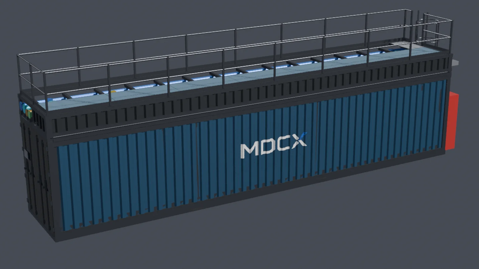
| Envelope | 14,000 × 2,438 × 3,490 mm | table ISO container envelope, MDCX module geometry |
| Footprint | 34.1 m² | derived 14.000 m × 2.438 m |
| Lead time | 90 days ex-works | claim C3 |
3D views
Orthographic and section views are generated from the published module geometry for this SKU. The interactive view is read-only — this is the standard configuration, not a configurator.
Geometry and schedules
- OpenUSD reference model —
DLC45-1800KW.usdc.xz
System boundary
The MDCX-supplied envelope is the container. Primary (utility) and secondary (facility) electrical sides meet at the transformer. Site responsibility begins at the published electrical and water interfaces.
Interface definition only. Implementation details are not published.
Power distribution
How power is broken down and distributed inside the boundary, and what the site must present at the connection point.
IT load against plant overhead
At: USA - Pennsylvania (PJM), 34 °C, Summer peak, 100% utilization, GB300 NVL72. The racks draw below the density ceiling at this GPU — 704 kW of rack headroom remains.
Plant consumers
| Consumer | Power | Share of facility |
|---|---|---|
| IT — liquid-cooled racks | 1056 kW | 82.2% |
| IT — air-cooled rack | 40.0 kW | 3.1% |
| Primary water pumps | 47.3 kW | 3.7% |
| CDU pumps | 40.0 kW | 3.1% |
| In-row CRAH fans | 5.3 kW | 0.4% |
| Dry cooler fans | 22.7 kW | 1.8% |
| Chiller compressor | 44.7 kW | 3.5% |
| UPS conversion loss | 11.0 kW | 0.9% |
| Distribution loss | 11.0 kW | 0.9% |
| Facility auxiliaries | 7.0 kW | 0.5% |
| Facility total | 1285 kW | 100% |
Plant overhead is 189 kW, 17.2% of IT, for a PUE of 1.172 at this point.
Single-line topology
Single-line topology (interface definition). Protection settings are not published.
No UPS in this SKU — UPS and battery are customer-supplied, outside the container boundary.
Ratings at the boundary
Ratings in this section are derived from the IT design load and the published PUE band. They size an interface; they are not measured results and are not claims-registry facts. Each derived row prints its formula.
C9 liquid PUE ≈ 1.15–1.20 is typical mid-climate only — not free-cooling or summer-peak. Confirm the site point in TCO / Liquid Cooling Designer. It is not an unconditional product band.
| Item | Value | Basis |
|---|---|---|
| IT design load | 1,800 kW | claim C28 |
| Facility load | 2,006.6–2,137.2 kW | derived 1,800 kW × PUE 1.115–1.187 |
| Connection capacity | 2,207.3–2,350.9 kW | derived facility load × 1.10 |
| Transformer capacity | 2,207.3–2,350.9 kW | derived sized to connection capacity |
Load schedule
A per-circuit load schedule is not published for this SKU. The topology above is the interface definition.
Interface definition only. Implementation details are not published.
Cooling distribution
How heat leaves the racks and reaches ambient: the loops, their design temperatures and flows, and where the plant switches from free cooling to mechanical cooling.
Heat distribution
At: USA - Pennsylvania (PJM), 34 °C, Summer peak, 100% utilization, GB300 NVL72. The racks draw below the density ceiling at this GPU — 704 kW of rack headroom remains.
| Heat path | Heat | Share of IT |
|---|---|---|
| Cold plate — direct liquid | 792 kW | 72.3% |
| Rear-door HX — water | 82.5 kW | 7.5% |
| In-row CRAH — chilled water | 221 kW | 20.2% |
| IT heat total | 1096 kW | 100% |
79.8% of the heat leaves on water at the cold plate and rear door; 20.2% is picked up as air by the in-row CRAH. Raising the liquid share moves load off the chilled circuit, which is the branch that needs mechanical cooling.
Heat split against the air / liquid ratio
The ratio is set by the server platform, not by the container. Each point moved off the air path is load taken off the chilled circuit — the only branch that needs mechanical cooling.
Loop schematic
Loops
| Loop | Supply | Return | ΔT | Design flow | Fluid |
|---|---|---|---|---|---|
| Technology cooling (TCS) — cold plate + rear door | 36 °C | 45 °C | 9 K | 171.3 m³/h | PG25 |
| Chilled water — in-row CRAH | 10 °C | 16 °C | 6 K | 32.8 m³/h | Water |
Heat rejection
Dry cooler, with a screw compressor above the switch temperature
| Item | Value | Basis |
|---|---|---|
| CDU rated cooling | 2,400 kW | table MDCX CDU selection |
| CDU units installed | 2 | table MDCX CDU selection |
| In-row CRAH installed | 4 | table MDCX in-row CRAH selection |
| In-row CRAH rated cooling | 218.8 kW | table MDCX in-row CRAH selection |
| In-row CRAH fan power | 10.4 kW | table MDCX in-row CRAH selection |
| CDU secondary flow | 207.6 m³/h | table MDCX CDU selection |
| CDU approach | 4 K | table MDCX CDU selection |
| Pressure drop | 195 kPa | table MDCX CDU selection |
| Pipe diameter | DN25 | table MDCX rear-door heat exchanger requirement |
| Switch temperature | 40 °C ambient | derived loop return 45 °C − dry cooler approach 5 K |
Interface definition only. Implementation details are not published.
Performance
PUE, WUE, and annual energy depend on site and workload, so they are not properties of the SKU. Solve this SKU at your own site:
Basis and disclaimer
Computed numbers in this document are operating-point results for the stated city, season, workload, and utilization. They are not guarantees or SLAs. Marketed numbers live in the claims registry.
Cited claims: C3 · C4 · C31 · C36 · C37 · C38 · C39 · C28 · C29 · C33.
Expansion block and first delivery are 90 days ex-works from receipt of down payment (C3, C4); on-site installation and commissioning 3–4 weeks (C36). Freight and customs are buyer-arranged; MDCX publishes no estimate (C39). Retired schedule and fleet-PUE claims are not restated.
Reserved items
This document publishes what a correct result looks like. It does not publish how MDCX produces it, or with what.
| Withheld | Statement |
|---|---|
| BOM, makes, models, suppliers | Bill of materials, makes, models, and suppliers are not published. |
| Control logic, alarm thresholds, tuning | Control logic, alarm thresholds, and tuning policy are not published. |
| Solver kernel | The solver kernel is not published. Operating conditions and result numbers are. |
| Manufacturing and quality path, takt | Manufacturing path, quality process, and line takt are not published. |
| Price and commercial terms | Price and commercial terms are not published. |